Curriculum
Science Grade XII Physics
Science Grade XII Physics
0/14-
Chapter 1: Electric Charges and Fields
 Preview
 -
Chapter 2: Electrostatic Potential and Capacitance
Preview
-
Chapter 3: Current Electricity
Preview
-
Chapter 4: Moving Charges and Magnetism
Preview
-
Chapter 5: Magnetism and Matter
Preview
-
Chapter 6: Electromagnetic Induction
Preview
-
Chapter 7: Alternating Current
Preview
-
Chapter 8: Electromagnetic Waves
Preview
-
Chapter 9: Ray Optics and Optical Instruments
Preview
-
Chapter 10: Wave Optics
Preview
-
Chapter 11: Dual Nature of Radiation and Matter
Preview
-
Chapter 12: Atoms
Preview
-
Chapter 13: Nuclei
Preview
-
Chapter 14: Semiconductor Electronics
Preview
Chapter 7: Alternating Current
|
Grade 12 Science | Chapter 7 Alternating CurrentMains electricity is alternating current. This chapter develops AC and its RMS value, components in AC circuits, the series LCR circuit and resonance, and the transformer.
|
|
Contents
|
1. Introduction: Alternating Current |
The electricity in our homes is alternating current, or AC, in which the current changes direction many times each second, following a smooth wave. This is different from the steady direct current of a battery. AC is used because it can be easily stepped up or down in voltage by a transformer, which makes it efficient to send over long distances. This chapter studies how AC behaves in circuits.
|
Core idea In AC the current reverses each half cycle. Its effective size is the RMS value, and in a circuit with an inductor, capacitor and resistor, a special resonance can occur.
|
2. RMS Values |
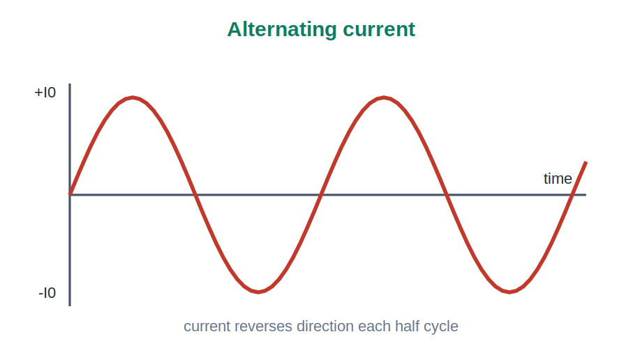
Because an alternating current is constantly changing, we describe its size by an effective value called the root mean square, or RMS, value. The RMS value is the steady direct current that would give the same heating effect. For a sine wave the RMS value is the peak value divided by the square root of two. The mains voltage quoted, such as 230 volt, is an RMS value.
|
Diagram 1 – Alternating Current
Fig 1. An alternating current follows a sine wave, reversing direction each half cycle. |
3. AC Through Components |
Different components respond to AC in different ways. A resistor behaves as in a DC circuit. An inductor opposes changes in current and so resists AC more at high frequency, an effect called inductive reactance. A capacitor lets AC pass more easily at high frequency, called capacitive reactance. These frequency dependent effects make AC circuits richer than simple DC ones.
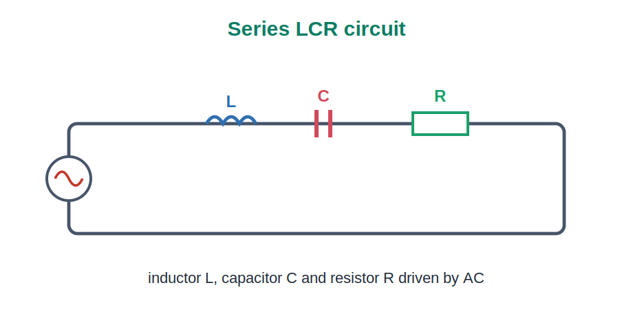
4. The Series LCR Circuit |
A series LCR circuit contains an inductor L, a capacitor C and a resistor R driven by an AC source. The total opposition to the current is the impedance, which combines the resistance with the two reactances. Because the inductor and capacitor affect the current in opposite ways, the impedance depends strongly on the frequency of the source.
|
Diagram 2 – Series LCR Circuit
Fig 2. An inductor, capacitor and resistor in series, driven by an alternating source. |
5. Resonance |
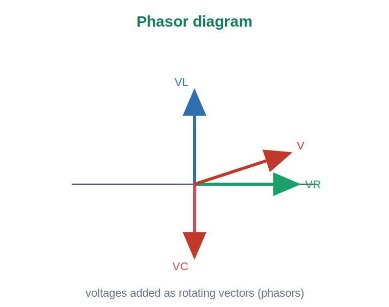
At one special frequency, the resonant frequency, the opposing effects of the inductor and capacitor exactly cancel. At resonance the impedance is at its lowest, equal to just the resistance, so the current is at its largest. This is the principle behind tuning a radio, where the circuit is adjusted to resonate at the frequency of the chosen station. The behaviour is often shown using rotating vectors called phasors.
|
Diagram 3 – Phasor Diagram
Fig 3. The voltages across L, C and R are added as rotating vectors, or phasors, to give the total. |
6. The Transformer and Power |
The transformer uses mutual induction to change an AC voltage. It has two coils on an iron core; the ratio of turns sets how the voltage changes, stepping it up or down. Transformers make it possible to send power at very high voltage and low current, which greatly reduces energy loss in the cables, and then to step it back down safely for use in homes.
7. Key Reasoning (Principles) |
|
Principle 1: RMS gives the effective value of AC Since AC keeps changing, its size is given by the RMS value, the steady current that would produce the same heating. |
|
Principle 2: Reactance depends on frequency An inductor opposes AC more at high frequency and a capacitor less, so the response of an AC circuit changes with frequency. |
|
Principle 3: At resonance the current is greatest When the inductive and capacitive effects cancel, the impedance is least and the current is largest, which is used to tune circuits. |
8. Worked Examples |
| Example 1 |
|
Q: What is alternating current? ▶ Show SolutionA current that changes direction many times each second. Answer: Current that reverses regularly. |
| Example 2 |
|
Q: Why is AC used for the mains supply? ▶ Show SolutionBecause its voltage can be easily changed by a transformer for efficient transmission. Answer: It is easy to transform. |
| Example 3 |
|
Q: What is the RMS value of an alternating current? ▶ Show SolutionThe steady direct current that would give the same heating effect. Answer: The effective heating value. |
| Example 4 |
|
Q: For a sine wave, how is the RMS related to the peak value? ▶ Show SolutionThe RMS value is the peak value divided by the square root of two. Answer: Peak divided by root two. |
| Example 5 |
|
Q: How does an inductor respond to high frequency AC? ▶ Show SolutionIt opposes the current more at high frequency. Answer: It opposes more. |
| Example 6 |
|
Q: How does a capacitor respond to high frequency AC? ▶ Show SolutionIt lets the current pass more easily at high frequency. Answer: It passes more easily. |
| Example 7 |
|
Q: What is the total opposition to current in an LCR circuit called? ▶ Show SolutionThe impedance. Answer: The impedance. |
| Example 8 |
|
Q: What happens at the resonant frequency? ▶ Show SolutionThe inductive and capacitive effects cancel, the impedance is least, and the current is largest. Answer: Current is largest. |
| Example 9 |
|
Q: Give one use of resonance. ▶ Show SolutionTuning a radio to a chosen station. Answer: Tuning a radio. |
| Example 10 |
|
Q: What does a transformer do? ▶ Show SolutionIt changes an AC voltage up or down using mutual induction. Answer: Changes AC voltage. |
9. Practice Sets A to D |
| Set A – Multiple Choice (Basic) |
|
1. Alternating current: (a) is steady (b) reverses regularly (c) does not flow (d) is DC 2. The effective value of AC is the: (a) peak (b) RMS value (c) average (d) zero 3. An inductor opposes AC more at: (a) low frequency (b) high frequency (c) zero frequency (d) never 4. Total opposition in an LCR circuit is the: (a) resistance (b) impedance (c) reactance only (d) voltage 5. At resonance the current is: (a) least (b) greatest (c) zero (d) reversed ▶ Reveal Answers1. (b) reverses regularly. 2. (b) RMS value. 3. (b) high frequency. 4. (b) impedance. 5. (b) greatest. |
| Set B – Short Answer (Understanding) |
|
1. What is alternating current and why is it used? 2. Define the RMS value of AC. 3. How do an inductor and a capacitor respond to frequency? 4. What is impedance? 5. What happens at resonance and where is it used? ▶ Reveal Answers1. A current that reverses direction regularly; it is used because its voltage is easily transformed for efficient transmission. 2. The steady direct current that would give the same heating effect; for a sine wave it is the peak divided by root two. 3. An inductor opposes AC more at high frequency; a capacitor passes it more easily at high frequency. 4. The total opposition to alternating current, combining resistance and the two reactances. 5. The inductive and capacitive effects cancel, so the impedance is least and the current greatest; it is used to tune a radio. |
| Set C – Application and Reasoning |
|
1. A sine wave has a peak current of 10 ampere. Find the RMS value. 2. Why is power sent at high voltage over long distances? 3. Why does a radio circuit need to resonate? 4. Why does the mains quote 230 volt rather than the peak? 5. Why does AC suit transformers but DC does not? ▶ Reveal Answers1. RMS equals 10 divided by the square root of two, about 7.07 ampere. 2. Because high voltage means low current, which greatly reduces the energy lost as heat in the cables. 3. So that at the chosen station’s frequency the current is largest, picking out that station. 4. Because the RMS value gives the effective heating value, which is the useful measure for appliances. 5. Because a transformer needs a changing flux, which AC provides, while steady DC does not. |
| Set D – Higher Order (Challenge) |
|
1. Explain why the RMS value, not the peak, is used to describe AC. 2. Explain why the LCR impedance depends on frequency. 3. Explain why current is greatest at resonance. 4. Explain how transformers reduce transmission losses. 5. A peak voltage is 325 volt. Show why the RMS is about 230 volt. ▶ Reveal Answers1. Because AC keeps changing, so a single steady equivalent, the heating value, is the meaningful measure rather than the brief peak. 2. Because the inductor’s and capacitor’s reactances change with frequency in opposite ways, so the total opposition varies with frequency. 3. Because at resonance the inductive and capacitive effects cancel, leaving only the resistance, so the impedance is least and the current largest. 4. By stepping voltage up so the current is small, the heating loss in the cables, which depends on the current, is greatly reduced, then stepping it down for use. 5. RMS equals 325 divided by the square root of two, which is about 325 divided by 1.414, giving roughly 230 volt. |
|
Chapter Summary
|
|||||||||||||||||||||||||||||||
| 8-Point Exam Quick-Check | ||||||||||||||||||||||||||||||||
|
||||||||||||||||||||||||||||||||
|
School Revise Virtual Lab Explore these ideas with interactive simulations and visual tools.
|
|
Class 12 Physics Chapter 7: Alternating Current, Complete Notes and Practice This revision guide follows the current NCERT Class 12 Physics syllabus and develops alternating current, covering AC and why it is used, the RMS value as the effective heating value, the behaviour of resistors, inductors and capacitors in AC circuits, the series LCR circuit and impedance, resonance and its use in tuning, and the transformer that reduces transmission losses, with three diagrams, ten worked examples and graded practice. Visit SchoolRevise.com to revise, practise and excel. |